VRF-Lite
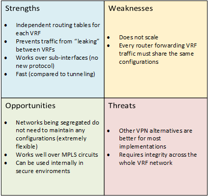
VRF-Lite*, or Virtual Routing and Forwarding Lite, is yet another VPN protocol that segregates traffic on a shared line, but as John Templeton said, “this time it’s different”. Most VPN protocols (e.g. GRE, L2TP, PPTP, etc) encapsulate the traffic once, and expand the traffic once it gets to its destination, and the routing between the two endpoints are seen as a tunnel. The encapsulated traffic never deals with any transit routing, it just sees the two ends of the tunnel as a single network.
VRFs don’t encapsulate, VRFs don’t use any new network protocol. VRFs is just a function of the router.
For each VRF, you get a new routing table. This allows a single router to route traffic for separate networks without having traffic “mix”. For example, an ISP could use a single router to route traffic for multiple customers.
*I will refer to VRFs and VRF-Lite interchangeably with the understanding that VRF-Lite is only an implementation of VRF.
Background Information
As described above, VRFs create a “virtual” routing table for each VRF. This routing table, for all intents and purposes, is a virtual router running inside of the router running the VRFs. For those familiar with virtualization, the router acts like a hypervisor for “guest routing tables”. Each VRF will have separate routing instances, and can even use overlapping IP addresses.
There are three steps to create a VRF. The first step is to create the VRF. This only makes a new routing table. When first creating the VRF, the VRFs routing table is empty, even if there were previously configured routes in the “host” routing table.
The next step is to assign interfaces to the VRF. The interfaces can be either physical (e.g. Gigabit, FastEthernet, etc) or virtual (e.g. Dot1q, GRE, MPLS, etc). Once the interface is assigned to the VRF, that interface is exclusively assigned to the VRF.
Finally, a new routing instance needs to be configured to route traffic for the VRF. This is done by creating, for example, a new OSPF instance with a new process number. Again, this instance is also exclusive to the VRF it’s assigned to.
Lab Summary
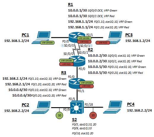
We will create a topology with two VRFs routed between four hosts (two per VRF), three routers, and a switch. The routers will all run both VRFs and route them separately. The switch will be connected to R3 as a trunk and maintain network isolation by switching them in two different VLAN (VLAN 10 and 20).
Topology
Configuration
- Create the VRF
- Assign the VRF to an interface
- Route over VRFs
Create the VRF
The first step is to create the VRF. Use the following command to provision both VRF green and VRF red.
(config)#ip vrf green
(config)#ip vrf red
Assign the VRF to an interface
A VRF is just a routing table at this point, no interfaces assigned, so no way to send or receive traffic. Beware that the command to assign a VRF to an interface may clear some existing configurations, especially the IP address of that interface.
Assigning a VRF to an interface
The following command will assign a VRF to a normal interface.
(config-if)#ip vrf forwarding green
Assigning a VRF to a sub interface
The following command will assign a VRF to a sub interface. Setting the encapsulation is required to for use over a sub-interface.
(config-subif)#encapsulation dot1q 10
(config-subif)#ip vrf forwarding green
Route over VRFs
Because each VRF has it’s own routing table, they each need their own routing process. The following command is used to enable OSPF routing over VRFs, but most routing protocols can be ran over VRF using a similar command.
(config)#router ospf 1 vrf green
Full configureations
click to expand
R1
R2
R3
S1
Conclusion
VRFs is a very powerful tool when creating complex networking topologies. They really show their usefulness when VRFs run over an MPLS circuit (future lab?). They can isolate networks, separate customers, and prevent route-leaking. There are many creative uses for a protocol that allows multiple routing tables and the ability to have overlapping IP addresses.