GRE is one of many Virtual Private Network (VPN) technologies. VPNs act like a conduit that runs between two (or more… foreshadowing!) routers where traffic can flow through as if the remote router is directly connected, even when its not. Where VPNs really show their hand is when we implement a layer of security on top of our GRE tunnel. This will protect all data flowing between sites.
How it Works
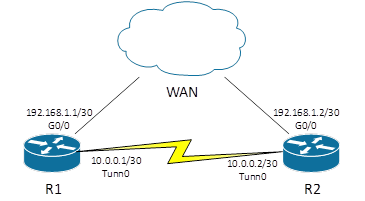
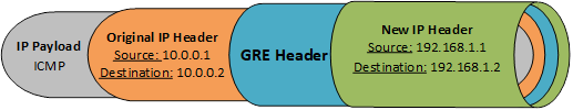
From the routers perspective, a GRE tunnel is just like any other interface: it has an IP address, it can be enabled or disabled, a routing protocol can be enabled on it, and anything else a normal interface can do. The only difference: there is no physical “tunnel” cable. It is a virtual link between the two devices. The magic of the GRE tunnel is in the GRE header. It takes the original packet, with the original IP header, and adds a GRE header and a new IP header. The IP header is sent to the destination interface of the other side of the tunnel. This “protects”/hides the GRE payload from any routing. Only the new ip header is routed.
How it Looks
Notice how the tunnel interface is listed as any other interface. It has an IP address of its own and is treated as any physical interface.
R1#show ip interface brief
Interface           IP-Address   OK?  Method  Status  Protocol
GigabitEthernet0/0  192.168.1.1	 YES  manual  up      up
Tunnel0             10.0.0.1     YES  manual  up      up
Notice how there is only one hop. No matter how many hops there will be on the WAN, the other side of the GRE tunnel is only one hop away – the hops in the WAN aren’t even visible. It looks like the other side of the tunnel is just on the other end of a physical interface.
R1#traceroute 10.0.0.2
Type escape sequence to abort.
Tracing the route to 10.0.0.2

  1   10.0.0.2        0 msec    0 msec    0 msec
If we were to examine the IP packet for this demonstration, it would look like this. GRE added a new header to the packet, so it could be routed over the WAN, but once it’s received by R2, the “New IP Header” is removed and sent to the tunnel interface.
How it’s Configured
Following the theme of “a tunnel is just another interface”, a GRE tunnel is configured right on the tunnel interface.
- Configure the tunnel interface
- Configure an IP address
- Configure the source port/address
- Configure the destination address
R1(config)#interface tunnel 0
%LINK-5-CHANGED: Interface Tunnel0, changed state to up
R1(config-if)#ip address 10.0.0.1 255.255.255.252
R1(config-if)#tunnel source g0/0
R1(config-if)#tunnel destination 192.168.1.2
R1(config-if)#no shutdown
It is customary/best practice to configure the tunnel source as a port, and the destination as an IP address. This is to prevent any address changes on the source port effecting the tunnel. On the other device, there should be a mirror image of the above configuration. In other words, the tunnel source on R2 should have the address 192.168.1.2, and the tunnel destination address should be configured with the exact address of R1’s GigabitEthernet0/0 interface. There are a few other ways a GRE tunnel can operate. The above configuration only supports IPv4 GRE tunnels. To setup an IPv6 tunnel, the tunnel mode command must be issued.